Track Current (IPC-2152) Calculator
| Name | Value | Units | Variable |
|---|---|---|---|
| Track Current | The current you want the PCB track to be able to handle. | ||
| Temperature Rise | The maximum desired temperature rise due to the current flowing through the track. 20-40°C is a common value for this. | ||
| Track Thickness | The thickness (height) of the track. This is equal to the thickness of the copper layer the track is on. This is also called the copper weight. Common values are 17.5um (0.5oz) or 35um (1oz). | ||
| Board Thickness | The total thickness of the PCB that the track is on. A standard PCB thickness is 1.6mm. | ||
| Is Plane Present? | Set this to "True" if there is a copper plane either above or below the current-carrying track, and then enter the distance to it in the "Plane Proximity" field. If there is no plane, set this to "False", and the "Plane Proximity" variable will be disabled. | ||
| Plane Proximity | The distance from the current-carrying track to the closest copper plane. If it is a 2-layer 1.6mm PCB, with the current-carrying track on one side and ground on the other side, then the plane proximity would be 1.6mm. For 4 or more layer boards, this value is likely to be much less. | ||
| Thermal Conductivity | The thermal conductivity of the PCB. This is normally hard to determine, but for most FR4 PCBs this is around 0.20Wm-1K-1. | ||
| Minimum Track Width | The minimum track width needed to carry the specified current without exceeding the given temperature rise. |
Intermediate Variables
| Unadjusted Track Cross-Sectional Area | The unadjusted cross-sectional area. This gets multiplied by the many modifiers to give an adjusted cross-sectional area. | ||
| Track Thickness Modifier | The modifier to adjust the cross-sectional area with based on the track thickness. | ||
| Board Thickness Modifier | The modifier to adjust the cross-sectional area with based on the board thickness. | ||
| Plane Proximity Modifier | The modifier to adjust the cross-sectional area with based on the proximity of a plane to the current-carrying track. | ||
| Thermal Conductivity Modifier | The modifier to adjust the cross-sectional area with based on the thermal conductivity of the PCB. | ||
| Adjusted Track Cross-Sectional Area | The adjusted cross-sectional area, which is equal to the unadjusted cross-section area multiplied by all of the modifiers. |
This calculator can find the minimum allowed PCB track width for a given continuous current. Takes into account the allowed temperature rise, copper track thickness, proximity to planes, total thickness of the PCB, and PCB material in accordance with IPC-2152.
The calculator uses equations built from the data provided in the IPC-2152 graphs. Data points were extracted from the graphs using WebPlotDigitizer (a great program by-the-way). Suitable trend lines were then fitted. In the case of the three variable graphs, trend lines were fitted to the coefficients of the first set of trend lines.
I believe the accuracy of the calculator (w.r.t. the IPC-2152 graphs) to be quite high, within the range of data provided by these graphs. Outside of this, extrapolation could become inaccurate quickly, due to the use of 5th order polynomial's being used to model some of the data (this was the best choice). Other graph were modelled with power equations of the form y=Ax^B, and are likely to be more accurate that the polynomial during extrapolation.
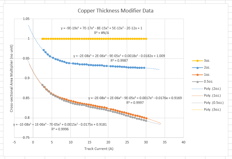
Below is an example of the trend-line fitting process. This image shows the "Copper Thickness Modifier" data from IPC-2152, along with 5th order polynomials being fitted to each data set. The data for the 3oz. copper weight is a horizontal line at y=1 by definition.
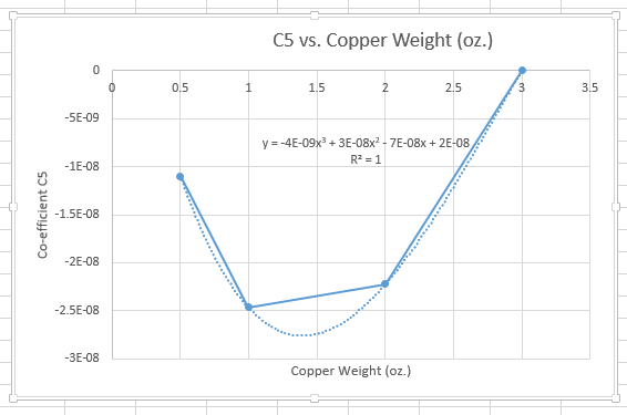
The co-efficients of the above trend lines were then plotted against copper weight (aka. track thickness). The graph below is co-efficient C5 (the co-efficient infront of x^5) against copper weight. These had their own trend lines fitted. Note that there are only four data points, AND the fitted trend-line is a third-degree polynomial, which is guaranteed to fit the data perfectly. This is probably the most dangerous part of the "discrete graphed data sets to continuous equations" conversion.
The current in assumed to be constant (DC). However, you can use the RMS value for a pulsed current as long as the pulses are fast enough.
The temperature of the PCB material should NEVER exceed the relative thermal index (RTI) of the material. This is defined in UL746B as the temperature at which 50% of the materials properties are retained after 100,000 hours.
Remember this calculator does not take into account other nearby heat sources.
This standard is designed to supersede the older IPC-2221A standard. It is designed to produce a more accurate track width calculation, but does require more variables. However, if you do want to use the older IPC-2221A standard, click here.